-40%
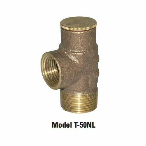
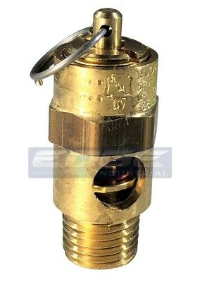
1/2" BRASS 75 PSI Relief Valve NEW Legend 1/2" T-50 NL PRS RLF VALVE 75-150
$ 6.64
- Description
- Size Guide
Description
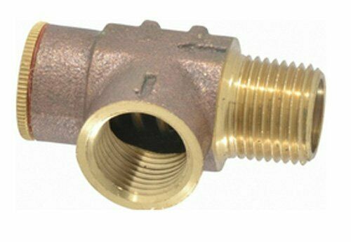
Legend 1/2" T-50 NL PRS RLF VALVE 75-150 SET @ 75# BRASSLEAD-FREE WATER PRESSURE RELIEF VALVE Model T-50NL MATERIAL SPECIFICATION PART MATERIAL SPECIFICATION 1 Access cap Lead-free forged brass UNS Alloy C46400 2 Cap seal Nitrilic-bonded non-asbestos fiber Commercial grade 3 Disc Lead-free forged brass UNS Alloy C46400 4 Spring Stainless Steel AISI Grade 304 5 Seat-spring piston Lead-free forged brass UNS Alloy C46400 6 Seat washer EPDM rubber Commercial grade, NSF approved for potable water 7 Seat screw Copper JIS H3260 ALLOY TYPE C2600W 8 Body Lead-free forged brass UNS Alloy C46400 DIMENSIONS Size A B C 1/2” MNPT inlet x 1/2” FNPT outlet 2.46 1.42 1.02 3/4” MNPT inlet x 1/2” FNPT outlet 2.48 1.42 1.02 Lead-free design is suitable for all no-lead potable water installations, in full compliance of all lead-free plumbing laws. Available with two factory pre-set water pressure relief pressures, to accommodate residential and commercial well applications: 75 p.s.i. and 100 p.s.i. Designed and calibrated for water well pressure relief, to prevent system damage. Adjustable relief pressures, from 75 or 100 p.s.i., to 150 p.s.i. Heavy-duty stainless steel coil-spring design ensures positive closure. Working Pressure, Non Shock (PSI) Cold working pressure (CWP): 150 psi up to 180°F Saturated steam (WSP): Not suitable for steam service Pictured Model T-50NL Cut-away Pictured Model T-50NL Side view Pictured Model T-50NL • Third-party tested and certified in compliance with U.S. Federal Public Law 111-380. • End connections conform to ANSI / ASME B1.20.1 • Not suitable for applications requiring an ASME-approved relief valve. The T-50 is not ASME approved. • Manufactured in an ISO accredited facility Adjustment procedure: 1. Remove knurled access cap (Part #1) 2. Mark the position of the screwdriver slot in the disc (Part #3), in relation to the body (Part #8); Using a permanent marker, make a reference mark on the top edge of the body, at either end of the slot. 3. With a large flat-blade screwdriver, turn the disc clockwise to INCREASE the relief pressure. One complete 360° revolution equates to a 25 p.s.i. increase: 75 p.s.i. factory setting plus three complete revolutions from the reference mark attains the 150 p.s.i. setting. 100 p.s.i. factory setting plus two complete revolutions from the reference


